Condition Monitoring of Power Plant- and Marine Diesel Engines
Part 1 - Introduction
1.1 General
In this present information, as well as in a number of subsequent chapters, we will describe from our experience how to investigate the technical behaviour of diesel plants including of the auxiliary systems and control and monitoring equipment.
We will determine the required equipment and explain how to use it properly. In additional we will explain how the results of the measuremenst can be used in order to get a complete system of preventive maintenance for the entire plant and the required repair works.
Due to this system the plant management will be in a position to plan and organize the measures which will optimize the operation by using measuring results of e. g. pressures, temperatures, set points of injection, fuel viscosity, wear and tear of the engine components etc.
Target of these procedures is to get information for example of
- Output and efficiency of the engine
- Indication of the begin of increasing wear and tear
- Condition of the components of the auxiliary systems like coolers, filters, separators, pumps etc.
- Trend analysis as a base for planned maintenance
1.2 Measuring Equipment and Points of Measurement
It has to be ensured that the list of data to be measured is complete. In the following chapters - that will be publshed in a 4-weeks interval - it will be described which equipment is required in order to get the necessary information. Sometimes special instruments are needed which are not available at site. In this case it is recommended to order a specialized company which has these instruments and skilled personal who can do this job.
The accuracy of the instruments should be as high as necessary; e.g. it makes no sense to measure the crankcase pressure with an instrument 0 – 10 bar because the pressure will be between 10 to 30 mbar.
Furthermore it should be ensured that the handling of the instruments is easy and the design according to the environmental conditions of a diesel engine plant.
It has to be decided which of the existing instruments should be used and when additional equipment should be employed in order to check the accuracy of the existing instruments as well and to adjust them if necessary.
It has to be ensured that the mobile measuring equipment can be installed easily because the measurement has to be repeated on a regular basis.
In the upcoming posts we will consider the following points separatly:
- Arrangement of measuring instruments
- Pressure, temperature, speed and torque measurement
- Commencement, fuel and lube oil consumption
- Fuel viscosity monitoring and control
- Evaluation of cylinder pressure diagrams
- Inspection of pistons and liners
- Inspection of cylinder head components
- Inspection of injection components
- Inspection of charge air supply and turbocharger
- Inspection of gear drive and camshaft
- Inspection of bearings
1.3 Diesel engine components
In general, the wear and tear behaviour of all diesel engine components is of importance. But there are some components, that are influencing the reliability of the engine directly and/or can cause consequential damages. For this reason we will consider the folllowing components separately within the next chapters:
- Injection pumps
- Injection nozzles
- Inlet and outlet valves
- Valve clearance
- Pistons including rings
- Cylinder liners
- Bearings
- Vibration dampers
- Turbochargers
- Charge air coolers
1.4 Most important points of measurement
- Barometric pressure air pressure [hPa]
- Charge air pressure before and after Charge air cooler [bar]
- Exhaust pressure after TC [mbar]
- Ambient temperature before TC [°C]
- Air temperature inlet engine [°C]
- Exhaust temperature after cylinder [°C]
- Exhaust temperature before TC [°C]
- Exhaust temperature after TC [°C]
- Cooling water before and after engine [°C]
- Lube oil temperature before and after engine [°C]
- Lube oil pressure after engine [bar]
- Interval of automatic filter flushing (lube oil and fuel) [1/h]
- TC speed [1/min]
- Engine speed [1/min]
- Engine torque after flywheel [Nm]
- Injection commencement: In angle degree before TD [C °]
- Combustion and compression pressure of each cylinder [bar]
- Cylinder liner temperature [°C]
- Main bearing temperature [°C]
- Fuel viscosity [cSt]
- Fuel flow to engine [m³/h] or [l/min]
- Crankcase pressure [mbar]
- Engine block vibrations [mm/s]
- TC vibrations [mm/s²]
- Oxygen content in exhaust gas [%]
- NOx [%]
- Fuel analysis by independent laboratory ./.
- Cooling water analysis by independent laboratory ./.
To be continued with Part 2 - Operating Measurements - Instruments and procedures
Part 2 - Operating Measurements - Instruments and procedures
2.1 Instruments
The aim of the proposed measurements hereinafter is, to get a realistic picture of the wear and tear status of the major engine components. All data, thus obtained and recorded shall be compared initially with the test bed data and the recorded commissioning - respectively sea trial data.
In order to be able to carry out a complete measurement of the engine operation data, the following instruments have to be provided:
| Instrument | Design | Accuracy | Range | Remark | |
| 1 | Thermometer, for surfaces | Infrared | 1.5% | min. 20°C - +40°C | contact-free |
| 2 | Pressure, digital | Gauge, abs. & digit. | 0.3% | -1 bar - +10 bar | min/max hold, HFO resistant |
| 3 | Tachometer | Laser, contact free | 0.1% | 1.0 rpm / 10.000 rpm | min/max hold |
| 4 | Electric Multimeter | Voltage, contact-free | 2.0% | 0 V - 600 V / 0 A - 20 A | min/max hold |
| 5 | Gauge, for cylinder pressure | Electronic | Class 1.6 | 0 bar - 250 bar | e.g. PREMET C-XL TDC sensor |
| 6 | Crank Shaft defllection | Mechanical or digital | ./. | 60 mm - 300 mm | Digital: option for liner ovality |
| 7 | Vibration | Velocity accelaration | 5% | 2 Hz - 1000 Hz | FFT* capability |
| 8 | Anemometer, digital** | Laser, contact-free | 0 m/s - 45 m/s | min/max hold | |
| 9 | Analyzer for exhaust gas*** | CO-, O2-, NOX-Sensors | 1.5%-0.2%-5% | <8000 ppm-<21 Vol%-<3000 ppm | EN 50379 |
* Fast Fourier transformation
** For air filters, ventilation and radiators
*** Only needed if evaluation capability is available
2.2 Procedures
Of course most of the above mentioned instruments have additional internal recording- and/or statistics features. But in regard to monitor and compare your actual engine condition against the new state condition, those features are not of importance for our purpose, the
preventive maintenance of large bore diesel engines for power plant- and marine diesel operation
Additionally it has to be ensured, that the all the instruments and devices - permanently installed on the engine by the engine manufacturer - are working properly. In particular these instruments are monitoring and recording the:
- exhaust gas temperature
- bearing temperature
- cylinder liner temperature
- turbocharger speed
- fuel viscosity and temperature
- fuel flow rate
During all the measurements that we recommend, the engine have to run with a load as close as possible to 100%. We recommend, that you start your measurements approx. 20 min after your engine reach the maximum load in order to get stable results.
Depending on the design of your plant, the specific type and brand of your engine and the permanetly installed monitoring system, the engine operation data is indicated and recorded in the control room. From our experience and in most cases, Wärtsilä´s "Operator Interface System - WOIS" or MAN´s "Engine Monitoring and Alarm System - EMAS" are the most common systems.
However, from our experience it is absolutely necessary - and should be taken for certain - to countercheck the indicated WOIS, respectively EMAS data with your mobile instruments at least once a year; because sometimes the remote instruments are not adjusted properly and/or broken – especially the thermocouples of the exhaust gas temperature. It is strictly recommended to maintain these instruments proper and carefully, because they can save the life of your engine.
The measuring and recording of your engine operation data should be repeated on a regular base, by your most experienced personal. Our recommodation is, to carry out this additional data collection at least once a month as part of your internal preventive maintenance prodecures. In order to get reliable and meaningful information about your real engine status those data should be compared to detect long term tendencies of the behaviour of your major engine components. A graph might be helpful.
Please feel free to download our attached form “Operation Data Protocol”. This form help to file, collect and evaluate the condition of your engine and the auxiliary systems.

....to be continued with Part 3 - Analysis of Measurements - The Indicatordiagram
Part 3 - Analysis of Measurements - The Indicatordiagram
3.1 Introduction
A Cylinder Pressure Indicator is something like a Intracardiac Catheter of a human being! In this chapter we will give answers to the 3 following questions:
- Why is the mesaurement of the pressure inside the combustion room, of each individual
cylinder in relation to the crankshaft angle, so important? - How to measure the cylinder pressure ?
- What are the diagrams telling us about the condition of the engine components and the
burning process ?
3.2 The purpose of combustion room pressure measurement
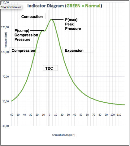
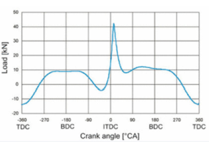
If anything is working well, the pressure inside the cylinder (combustion chamber) is increasing continuously; due to the compression work of the piston. During the compression process, the temperature is increasing continuously and finally the injected fuel will be ignited. For the ignition, energy is needed and therefore the pressure diagram shows a buckle in exactly this moment. After the ignition the fuel-air-mixture volume will increase explosively. Thus, this power accelerates the piston down and the pressure in the cylinder will expand.
The diagram on the left is showing the ideal curve of a new engine, tested on the test bed or right after proper commissioning at site. Each deviation of the cylinder pressure from this ideal curve will cause:
- Higher fuel consumption
- Higher exhaust gas temperatures
- Higher wear and tear of the components, involved into
the combustion process - Poor combustion with higher content of carbon residues
which creates fouling of the turbocharger - Air supply is disturbed and the combustion quality is going
down even more
There are a lot of reasons for these deviations such as:
- Cylinder liner and/or piston rings, worn out
- Injection pump, too low injection pressure due to wear and tear
- Injection nozzle, worn out or contaminated
- Injection timing , wrong adjustment - too early or too late
- Air supply to the cylinder, too low
- Fuel (sluggish fuel), ignition delay
With the right interpretation of the specific character of these deviations, possible failures or malfunctions -either at the engine itself or the surrounding auxiliaries - can be located and eliminated.
3.2.1 Procedure of the Cylinder Pressure Measurement
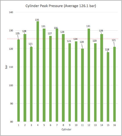

The column diagram shown on the left (Fig. 3.2.1) was the result of a measurement to determine the Maximum-Ignition-Pressure for each of the 16 cylinders at a power plant engine. At pressures of 180 bar, the deviation between the individual cylinders should not exceed 5 bar, thus, it can easily be seen that - in this specific case - it was urgently required to investigate in detail for all possible reasons that can cause this impermissible high deviation.
This example is a real one and was taken from us at an engine just infront of the general overhaul. It took us a couple of days to carry out all the works that were necessary to get the engine back into normal operation.
In case you currently have no measuring device in your engine plant available but you intend to buy one, please think about to invest into a digital pressure indicator. Only with this kind of equipment, you will be able to measure the pressure curve against the crankshaft angle. And only with this additional information out of the measurement, you will be able to determine the required steps to get your engine, either back into proper operation or just to carry an appropriate and professional engine service.
The measurement should be done at least every 3 months with the engine running at 100% of the load - respectively the load that is designated to your specific engine plant .
The restriction "...that is designated..." we made, because power plants - operated in altitudes higher than 800 m - might be limited to a lower specific load by the engine maker. This, in order to avoid excessive engine problems by an improper coursed combustion process; caused by the natural lack of oxygen in those altitudes.
The measured data should be continuously compared against the "As-New" data and tendencies should be observed. Additional measurements shall be made if:
- Exhaust gas temperature is increasing or decreasing
- Fuel consumption increases
- Correctness of the fuel rack position of each individual
injection pump is not ensured.
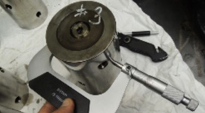
Before carrying out the combustion pressure measurement, the indicator cock has to be checked if all the thread of each individual cock is in order and has no damages to take the swivel nut from the indicator instrument.
Assumed that all threads are in good order it is necessary to open the cock for at least 3 strokes before the measurement is carried out in order to blow out carbon residues and moisture.
Independently what kind of measuring device is used:
- a spring diagram indicator,
- a peak pressure indicator with a pressure gauge or
- a digital elecronic indicator,
It is sufficient to indicate 10 combustion strokes to get the correct indication for a device internal analysis. Of course, it depends on how many cylinders you have to check during one step.
When a 6 or 8-cylinder engine has to be checked at once or the double amount of a cylinder of a Vee-type engine, after a while it may happen - especially by using digital devices - that they overheat and stop automatically the indication process. A spring indicator device can get a sticking movable piston for the reading stroke.
There are two possibilities to prevent this problem:
- If the measurement process is done by two people, one person is always ahead and does the necessary cleaning blow of the indicator cocks.
In this case you have the possibility to do at least the measurement of 18 cylinders in one step. - If your instrument is overheating, you have to cool it down with a low flow of pressed working air for about 10 – 15 minutes.
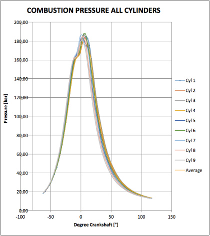
From our experience we recommend, that you summarize all the individual diagrams into just one single sheet; as it it shown in Fig. 3.2.2. This enables you to detect the difference(s) between the individual cylinders much easier.
3.3 Recognize - and troubleshooting
3.3.1 Late Ignition
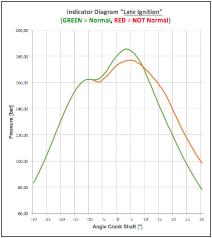
Late Ignition - Indications:
- Peak pressure low and after TDC
- High exhaust gas temperature
- Combustion during expansion
- Black smoke in exhaust gas
- Sometimes a loss of power
Late Ignition - Consequences:
- Increased fuel consumption
- Reduced lifetime of the exhaust valves
- Reduced lifetime of the piston crowns
- Environmental contaminaton due to high particle emission
Late Ignition - Causes:
- Fuel supply, too slow due to fouled injector
- Check the injector
- Fuel quality, poor
- check your fuel treatment, send a sample to an independent
laboratory
- check your fuel treatment, send a sample to an independent
- Cylinderliner, too cold
- Check and adjust the liner temperature
- Fuel pump, wrong timing adjustment
- Check and adjust in accordance to the engine maufacturers
advise
- Check and adjust in accordance to the engine maufacturers
- Combustion pressure, too low due to worn out cylinderliner and/or piston rings
- Compare the dimensions and clearances in regard to the given wear limits
- Combustion air supply, too low
- Measure the content of the remaining oxygen in the exhaust gas
or at the combustion air filter inlet and compare that measure-
ment against the "As New" condition.
- Measure the content of the remaining oxygen in the exhaust gas
3.3.2 Leaking Fuel Injector
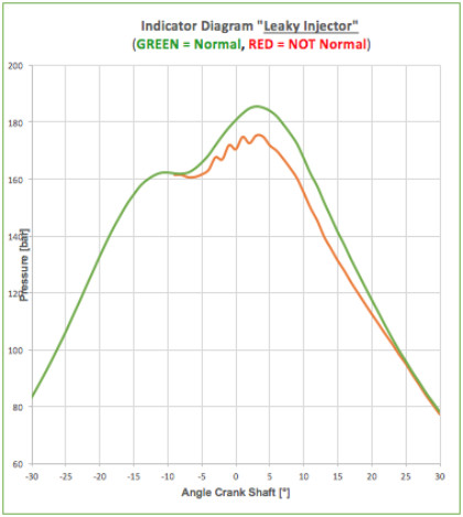
Leaking Injector - Indications:
- Peak pressure too low
- Pressure after TDC, wobbling during expansion
- After burning, disturbed
- Fuel consumption, increasing
- Pressure vibrations in fuel pipes abnormal high
- Knocking sounds, sometimes
Leaking Injector - Consequences:
- Vibration damages at the injection pipes
- Reduced lifetime of the piston crowns
- Fuel consumption, increasing
Leaking Injector - Causes:
- Leaking fuel injector
- Check the injector at the workshop test bed and replace if necessary
- Worn out or clogged injection nozzle spray holes
- Check the nozzle at the workshop test bed and replace if necessary
3.3.3 Early Ignition
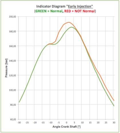
Early Ignition - Indications:
- Peak pressure too high
- Exhaust gas temperatures too low
- Fuel consumption, decreasing
- NOX emmissions, increasing
Early Ignition - Consequences:
- Parts inside the combustion chamber will be overheated. The lifetime
of the affected engine components will be reduced. - Knocking sounds comes out of the engine due to heavy loads
that are passed to the bearings via the running gear. - Shock loads and vibrations may result in an engine damage.
- Exhaust temperatures will be reduced because the combustions
starts long before it is supposed.
Early Ignition - Causes:
- Incorrectly adjusted or accidentally changed fuel pump timing
- Check and adjust
- Damaged or incorrectly setup of the fuel valve and/or fuel injector
- Check and adjust
- Fuel with easy flammable components
- Fuel quality to be checked by independent laboratory (may be harmful components are mixed to the fuel for illegal waste disposal).
3.3.4 Partly Clogged Fuel Valve
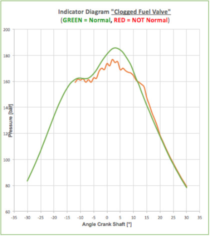
Partly Clogged Fuel Valve - Indications:
- Peak pressure, too low
- Exhaust gas temperature, too low
- Loss of engine power, due to too low fuel supply
Partly Clogged Fuel Valve - Consequences:
- Loss of engine power.
- Cracked injector, caused by too high pressure in the nozzle tip.
Partly Clogged Fuel Valve - Causes:
- Contamination of the fuel oil and/or improper purification
- Check and adjust the separators
- Check and exchange the filters and/or the filter candles
- Carry out a fuel oil analysis at an independent laboratory
- Carbon formation at the injector tip
- Check and clean.
- Check cooling effincy
- Carbon deposits on the fuel valve due to overheating
- Check cooling effincy of the injector
3.3.5 After Burning
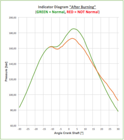
After Burning - Indications:
- Exhaust gas temperature, too high
- Peak pressure, too low
- Pressure at the end of burning, too high
- Smoke emissions, increasing
- Turbolader surging, sometimes
- Liner temperature, increasing
After Burning - Consequences:
- High particle emissions effect the environment
- Too high temperatures in the combustion chamber will cause:
- Additional burning of luboil
- Increased wear and tear of the cylinder liner, the piston crown and piston rings
- Unburnt carbon deposits will cause:
- Fouls of the exhaust gas system
- Damages at the exhaust valves and valve seat rings
After Burning - Causes:
- Slow fuel combustion process
- Carry out a Fuel-Combustion-Analysis.
- Poor fuel oil quality
- Carry out a fuel oil analysis at an independent laboratory.
- Fuel oil temperature is too low
- Check the final preheater and viscosity controller by means of
the fuel analysis and measure the temperature.
- Check the final preheater and viscosity controller by means of
3.3.6 Low Compression
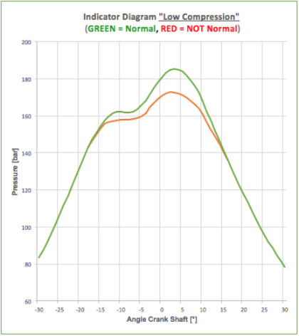
Low Compression - Indications:
- Compression pressure, too low
- Pressure peak, too low
- Power of the engine, decreasing
Low Compression - Consequences:
- Increased fuel oil consumption
- Loss of engine power
Low Compression - Causes:
- Improper combustion
- Carry out a Fuel-Combustion-Analysis.
- Combustion air supply too low
- Measure the content of the remaining oxygen in the exhaust gas or the air speed
at the combustion air filter inlet and calculate flow rate and compare with condition “As-New”. - Check the charge air cooler pressure drop
- Check the turbocharger speed, if too high, clean the nozzle ring.
- Measure the content of the remaining oxygen in the exhaust gas or the air speed
- Air leakage between the liner and the piston rings
- Dismantle the cylinder head and piston. Check the dimension
of the piston rings and cylinder liner in regard to avoid that
the wear limits have been exceeded already.
- Dismantle the cylinder head and piston. Check the dimension
Summary
The information above shows how important and significant the Indicator Pressure Diagrams are.
It is possible to detect a lot of failures which are influencing the efficiency of the engine and the lifetime of their components.
By carrying out these cylinder pressure measurement on a regular basis, the management of a vessel or a power plant has a powerful instrument to reduce the operational costs and to plan maintenance works in advance.
....to be continued with Part 4 - Pistons
Part 4 - Pistons
4.1 Introduction
This chapter will focus on pistons, respectively piston components for large bore Diesel engines in Marine- and Power Plant applications.
Today, modern pistons are beeing far away from just beeing "a piece of metal in the engine" that pushes down the connecting rod in order to generate the crankshaft rotation. There are other requirements as well that a piston must fulfill in order to ensure proper engine operation.
Based on the patent of her sister company MMS, more than 80% of the piston crowns that SECO is producing are so called WearResist® piston crowns. By using our piston crown the wear and tear of the ring grooves - due to combustion residues and the thermal load - is significantly reduced.
In this chapter, we will give answers to the 3 following questions:
- How to avoid thermal overload of the piston crown ?
- Why are the auxiliary systems of an engine plant that important ?
- Which engine components are influencing the lifetime of the piston ?
4.2 Pistons for 4-stroke diesel engines in general
The piston, as an engine component with the highest stresses during engine operation, has been continuously developed since decades now; in order to withstand the increasing stresses due to higher firing pressures and the aggressive compounds of the heavy fuel (HFO).
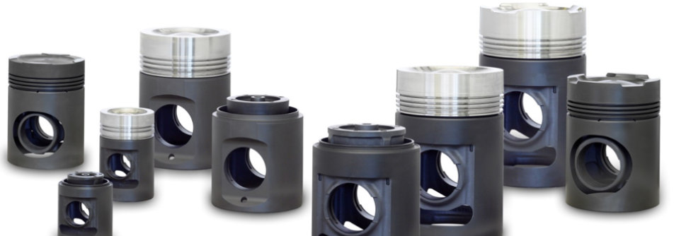
Neglecting some "ancient" piston types that are may be still existing somewhere in the field, we distinguish 4 piston designs that are different in principle:
- 1-Built- or composite piston - with a steel crown as the upper part (piston crown) and
an Aluminum, gray cast- or nodular cast iron as the lower part (piston skirt). - 2-Monobloc piston - made out of nodular cast iron.
- 3-Built- or composite piston - with a steel crown as the upper part (piston crown) and
a casted Aluminum piston skirt as the lower part. - 4-Monobloc piston - made out of an Aluminum casting with casted-in ring carrier
for the piston ring(s).
| Piston design principles | Material | Mean effective pressure [bar] | Mean piston speed [m/s] |
| 1-Built/Composite | NCI/Steel | 27.0 | 7.4 - 12.5 |
| 2-Monobloc | NCI | 17.0 - 22.0 | 7.0 - 14.0 |
| 3-Built/Composite | Aluminum/Steel | 15.0 - 24.0 | 8.0 - 10.5 |
| 4-Monobloc | Aluminum | 11.0 - 21.0 | 7.4 - 13.8 |
4.2.1 The aims of piston development
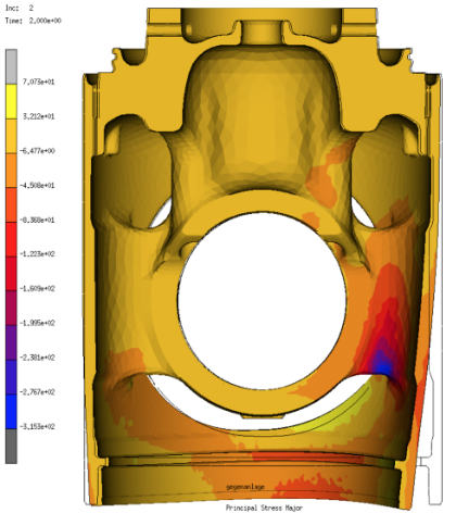
In the late 1980´s, the first CAD-Systems were introduced into the design offices of the engine manufacturers.
In parallel with the incredible speed of the computer development a wide range of additional software design tools were developed.
Nowadays, this software is able to simulate, calculate and consider the consequences of induced mecanical and thermal stresses into a new piston design; long time before the first piston will be produced.
The aims of the piston deverlopment:
- Sufficient fatigue strength against all static, dynamic and thermal
loads that are generating stresses into the piston components. - Sufficient cooling of the piston against the high ignition temperatures
of up to 1.800°C - To seal and hold the combustion gases and the firing pressure in the
combustion chamber (together with the piston rings) and to avoid the
penetration of Luboil from the Crankcase and cylinder liner wall - Good guidance of the piston in the cylinder liner
- High wear and tear resistance of the piston grooves
- Stability against the aggressive compounds of the HFO
With the right interpretation of the specific character of these deviations, possible failures or malfunctions -either at the engine itself or the surrounding auxiliaries - can be located and eliminated.
4.3. Piston damages
4.3.1 Insufficient fuel treatment
From our experience, one of the most common causes for premature wear at the piston, respectively the piston ring grooves (and other engine components as well of course) is an insufficient treatment of the fuel....for what reason ever.
Unfortunatly in many power plants it seems not to be for certain, that the attention that is paid to the engine directly is the same, that is paid to the fuel supply- and treatment peripherie of the engine.
Main causes for an insufficient fuel treatment:
- Settling tanks, too small or simply not existing
(easily to check by your own...) - Separator, too fast fuel flow caused by wrong adjustment
(a too high adjusted fuel flow easily degrades the
separator to an expensive pump only without separation
effect) - Filter, damaged
(check the filters on a regular base and never "repair"
a filter just to save small money. Otherwise you have to
spend big money at the other end...)
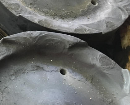
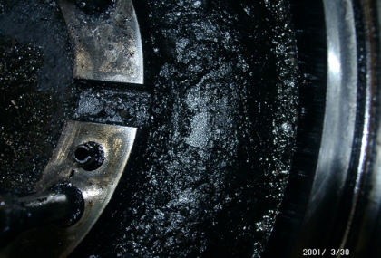
Typical damages due to insufficient fuel treatment :
- The piston crown burns off due to burning fuel on the
surface of the piston crown - The piston rings are breaking because the residues are
blocking the free ring movement in the groove - The piston crowns heat transfer management is heavily
disturbed due to cracked luboil residues, sticking on
the inner cooling surface of the piston crown.
Prevention against deposits on the crown :
- Make sure that your fuel (we assume it´s HFO) stays at
least 12 or even better 24h in your settling tank at 70°C. - Run your separators with a flow rate that is as low as
possible!
(Otherwise you just use it as an expensive pump only.) - Make sure that the injection viskiosity is in accordance
within the range, that is advised in the operation manual
of the engine maker.
From our experience, one of the most common causes for premature wear at the piston, respectively the piston ring grooves (and other engine components as well of course) is an insufficient treatment of the fuel....for what reason ever.
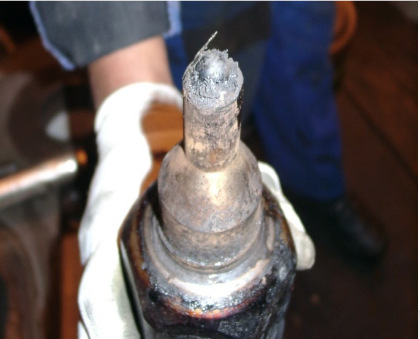
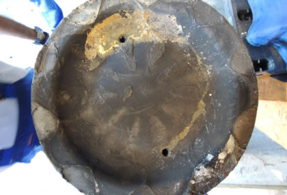
4.3.2 Incorrect fuel injection
Caused by insufficient fuel treatment
As already mentioned above, an insufficient fuel treatment is not only damaging the piston crown of course. The proper function of the fuel injection equipment will also be impaired.
The injection bores in the fuel injection nozzle will be clogged. And because the fuel flow rate is constant, an increased fuel speed of the remaining unclogged nozzle bores is the result (picture 4.3.2-1).
When this happens, the injected and accelerated fuel will reach the surface of the piston crown and creates a continious overheated hotspot at the piston crowns surface. (picture 4.3.2-3)
At this moment, the heat managment of the piston crown is heavily disturbed and the cooling oil - inside the cooling chamber of the piston crown - starts cracking and an insultion layer - consisting of cracked cooling oil - will be built up (picture 4.3.2-2).
Now the situation start to escalate. The heat of the combustion- respectively the firing process (...just to remind: we talk about temperatures of up to 1.800°C) cannot be exchanged properly to the cooling oil, because the inner cooling surface of the crown is already insulated by a layer of cracked cooling oil. The material of the piston crown start melting through with all the known consequences.
Finally this is, what we call "Hot Corrosion of a piston crown".
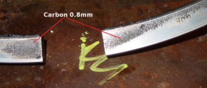
Investigations that we have carried out in a lobaratory in order to tetermine the insulating effect of a carbon layer, that is sticking on the inner surface of the piston crown, have produced the following results:
- Carbon residues have a 50 - 400 times worse thermal conductivy than high alloyed steel
- Carbon residues are a remarkable thermal insulator
- 1 mm thickness of oil deposit on surface is equal 80 mm thickness of steel (rule of thumb)
Caused by fuel impingment
Another reason for piston damages caused by incorrect fuel injection is a very simple one....and more frequent than you may think:
The use of wrong nozzles and/or the use of wrong fuel injector sleeves!
From our experience it happens, that during maintenance injections nozzles are installed that have the wrong spray angle. Similar happens with the injector sleeve; simply a wrong one will be installed and this cause a wrong position for the injection nozzle.
Both mounting errors are causing a so called "fuel impingment". As a result of this, the damage pattern at the piston crown is similar to the pattern that occurs due to insufficient fuel treatment.
How to prevent fuel impingment ? It´s easy...
- Check the spray pattern/picture of all injectors before instllation
- Buy your injection equipment not at the cheapest supplier but at
at the most cost effective one. - Check the position of the nozzle tip while installing in the cylinder head
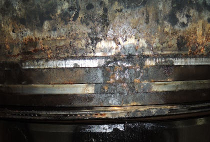
4.3.3 Water in the combustion chamber
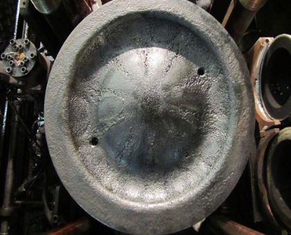
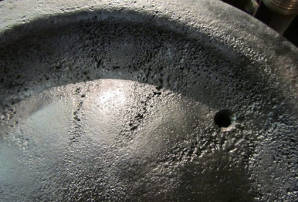
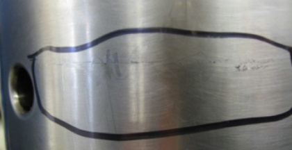
Because of the unique damage pattern, this problem can be easily determined by carrying out a visual inspection.
If there is a high amount of water in the combustion chamber, the water will evaporate during the ignition (not earlier, because the pressure is too high) and the combustion will be disturbed due to the volume of the existing steam.
In the beginning of the next cycle - when the intake air comes into the cylinder now - this water steam condensates. The steam that has condensated on the surface of the piston crown creates a vacuum. This
Causes for water in the combustion chamber :
- Crack of the exhaust gas valve seat
- Leak of cooling water through the sleeve of the injector
- Leaking sealing ring between cylinder liner and head
- Insufficient water removal from the fuel by the separators
Prevention against water in the combustion chamber :
- Check the level in the cooling water tank on a regular
basis. Record the amount of water that must be added
and start searching for the reason if the amount is increasing. - Ensure that the position of the sealing ring between the
cylinder liner and head is correct and check that the shape
of the ring is still in order. - Ensure proper fuel treatment in accordance to 4.3.2.
- Ensure proper drainage of combustion air duct inside the
engine. - Take care for a sufficient intake air temperature in order to
avoid feeding the combustion process with high humidity. - Take care that the water trap is in order and the drainage
is working properly either in automatic and in manual
operation.
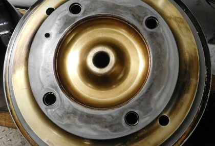
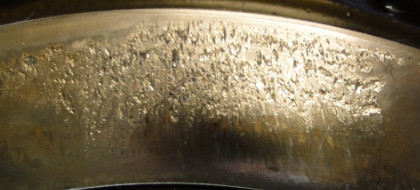
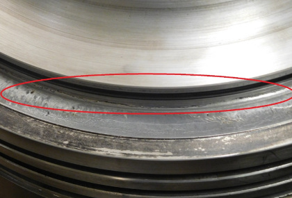
4.3.4 High-temperature corrosion due to the fuel quality
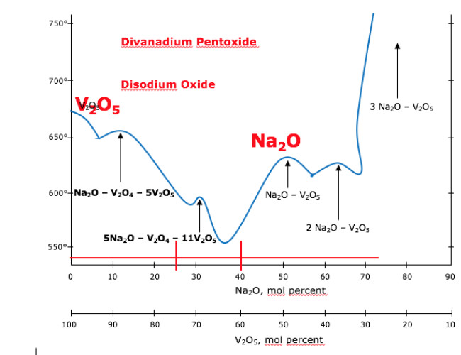
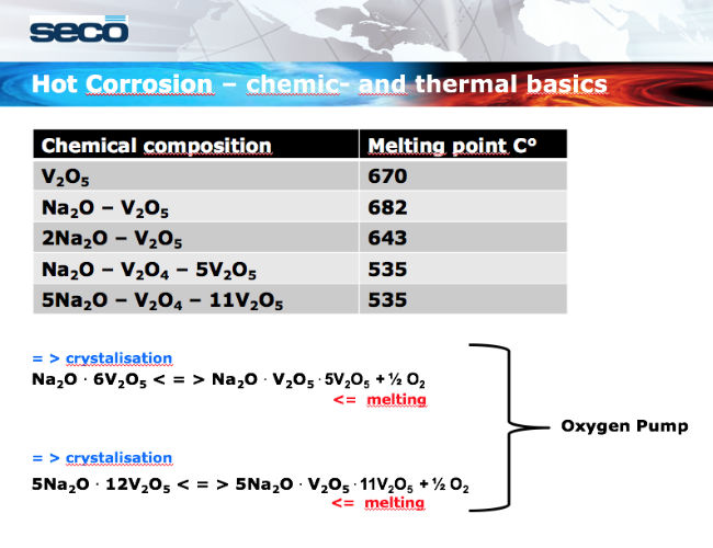
Usually, the supplied fuel is escorted with the chemical elements Vanadium and Sodium. During engine operation and under certain conditions, those elements are forming salts; like f.e. "Divanadium Pentoxide" and "Disodium Oxide".
During combustion, these salts are condensating on the surface of the piston crown and absorbing Oxygen out of the atmosphere of the combustion chamber. Then, this Oxygen is diffusing continiously into the material of the piston crown and destroys it on medium term.
This destructive process is well known as the "Oxygen-Pump" and must be avoided for anyhow.
For detailed information about the relationship between the fuel injection quality and the occurence of High-Temperature-Corrosion, please visit the "Lectures & Technical Information" section on our download page.
Prevention of High-Temperature Corrosion caused by the fuel :
- If the fuel analysis includes Vanadium and Sodium, counter-
check the provided analysis with an independent laboratory.
Reject the fuel if the relation Na/V<25% with Na<100mg/Kg.
(Check your supply agreement wit the fuel supplier first!) - Reduce the engine load if the exhaust gas temperatures
are too high. Maintain the cooling and the air supply system
as soon as possible. - Make sure that the water separator, installed after the charge
air cooler is working properly. - Clean the inner cooling surface of the piston crown as close
to the "as new" condition at each carbon service that you
carry out at the piston.
4.3.5 Burn-off due to too high combustion temperatures


Too high combustion temperatures can easily been recognized, because too high exhaust gas temperatures are the consequence.
The occurring damages at the piston are the same than described in 4.3.4. So they must not be repeated here once again. Instead of repaeting let us go directly to the possible prevention measures:
Prevention Measures to avoid too high combustion temperatures:
- make sure that the combustion air supply to the engine is
sufficient by:
- proper combustion air filter
- clean the charge air cooler
- set the cooling water inlet temperature as per design
- set the lube oil temperature as per design
- clean the nozzle ring of the turbo charger and do not
use worn out nozzle rings
- the exhaust gas back pressure should not exceed 30 mbar
- ensure a correct charge air pressure - check if the injection timing is correct
- check if the injection nozzles are in good condition
- if everything seems to be in order, then check the fuel
combustion behaviour (e.g. by Veritas Petroleum Services) - reduce the engine load if high temperatures cannot be avoided
by other measures.
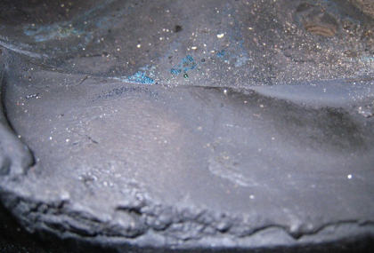
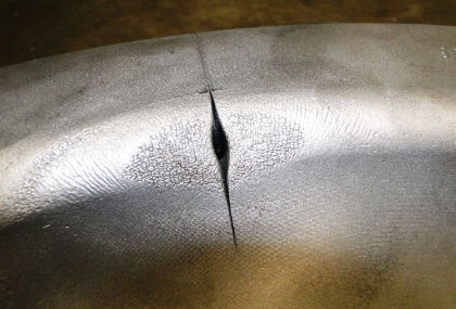
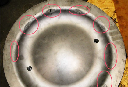
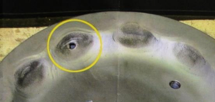
4.3.6 Incorrect tensioning between piston skirt and crown
If the tension between piston skirt and piston crown is - for what reason ever - too low, "fretting corrosion" or more precisley "micro cavitation" - caused by micro movement between the piston skirt and the piston crown - can occur.
There are two main mechanisms for wear of the seats.
Friction welding
- Fretting arises by microscopic friction welding due to lateral movement between piston crown and piston skirt. The microscopic peaks of their material will weld together and broken up immediately. Material from the softer piston skirt breaks out during this process, what shows the fretting marks.
Cavitation
- Usually, there is a small conical gap between piston crown and skirt. This gap should be closed during the whole operation. If there are small deviations from the ideal geometry of this gap, it cannot be closed. We can observe a breathing of the piston crown on the skirt.
That means, that the gap is alternating between opening and closing. During opening cooling oil will be sucked in the gap and pushed out again when closing. A very thin oil film will remain on the seat surface.
During the next gap opening the hydrostatic pressure in this oil film lowers very fast and cavitation bubbles can occur. They will collapse immediately again, which causes a shock to the seat surface and destroying it therefore.
Once started, this destructive process will damage both involved seat areas. Simultaneously the indicated geometry of the skirt´s seat area - specified by the engine- respectively specified by the piston maker) will be changed.
If this process continues - at the end of the day - initially the piston can be destroyed (see 4.3.6-3 and 4.3.6-4).
And even more worse, the risk of a serious engine damage will increase, e.g. due to cracked studs or screws.
Prevention of fretting between skirt and crown:
- Always new assembling parts parts must be used for each piston
assembling. (e.g. after carbon service has been carried out) - Make sure that the fastening procedure, described in the engine
makers manual, will be applied exactly. - Take care that the torque wrench that is used for the screw tightening
is in proper condition and has been calibrated on a regular basis. - Remove fretting marks before re-assembling carefully by means of
an oilstone. (max. 30% of the mating surface) - Check the convexity of the skirts seat area by means of a straight
edge, respectively in accordance to the indication of the piston skirt
drawing.
4.4 Summary
In large bore diesel engines, operated on marine vessels or in power generation plants, the piston is one of the most highly stressed components. Only the flawless function of the piston, despite the enormous mechanical and thermal loads, ensures a continuous and safe engine operation.
The lifetime of a piston (and as well the lifetime of all components that are involved in the combustion process) can be extended tremendously, when overheating can be avoided.
....to be continued with Part 5 - Piston rings
Part 5 - Piston rings
5.1 Introduction
Piston rings are the seals between the combustion chamber and the crankcase. If they fail - for what reason ever - a serious damage to the entire engine can occur.
In this chapter, we will give answers to the following questions:
- Why are piston rings that important for the proper function of an engine ?
- How are piston rings designed ?
- How can be detected that a piston ring is not working properly ?
5.2 Pistons ring functions
A piston ring is nothing else, than a casted seal out of an iron based alloy.
However, in order to ensure all the required properties/characteristics of a piston ring, it is necessary to add some alloying elements into the liquid iron prior to the casting process. The characteristics of a piston ring, or rather, the main tasks of a piston ring are:
- to seal the combustion chamber against the crankcase
- to transfer the combustion heat heat transfer from the piston to the cylinder liner
- to control the lub oil consumption of the engine
The thermal expansion coefficient of the ring should be similar to the cylinder liner in order to get a constant clearance between liner and ring.
In general there are two different kinds of piston rings:
- Compression rings are providing a gas seal; to seal the high pressured
combustion chamber against the crankcase. - Oil scraper rings are controlling the lube oil supply to the cylinder liner
If you are interested into more detailed information about existing piston ring designs, please have a look into the German DIN 24909.
In order to compensate a decreasing radial tension during his lifetime (caused by the extreme thermal conditions during engine operation), an unequal radial tension is introduced into the piston ring by the manufacturing process.
Sounds difficult ? But it isn´t.
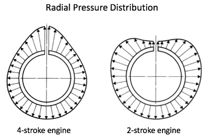
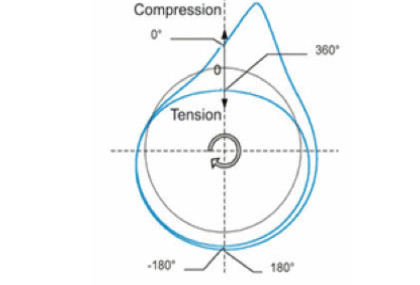
New piston rings does have a positive ovality which generates an uneqal radial pressure distrubution after assembly; as shown in picture 5.2 on the left.
For 4-stroke engines the tension peak is always located at the piston ring slot and generates this typical graph that is well known as the "Pear-Graph" of a piston ring. This typical distribution of the radial tension is also responsible to reduce the "Flutter Tendency" of the piston ring while engine operation.
To complete this topic you will find the typical stress distribution of a piston ring for 2-stroke engines in picture 5.3. on the left. Since this tension distribution graph looks very similar to an apple, this diagram is also well known as the "Apple-Graph" of a 2-stroke piston ring.
5.2.1 Compression rings
Compression rings are the only seal between the combustion chamber with pressures up to 250 bar and the crankcase with nearly ambient pressure. In addition to their main task - to seal against the crankcase - additionally, the compression ring(s) are influencing the oil film at the cylinder wall.
To avoid the overheating of the piston crown, the compression ring(s) are responsible as well for an undisturbed heat transfer from the piston crown to the cylinder liner in order to avoid overheating of the piston crown. The 1st (compression) ring of course, gets the highest heat load from the compression of the combustion air and the burning process.
The 1st compression ring is always "the victim" of the highest wear and tear due to:
- a thinner oil film at the upper part of the cylinder liner
- the high combustion temperatures
- the aggressive compounds of the fuel (Sulphur and Carbon deposits)
In order to prevent too high wear and tear, today´s standard execution are compression rings with a chrome- or chrome ceramic layer.
Instead of the common aluminum oxide particles in the chrome ceramic layer, small diamonds can be used as well. Thus, the wear resistance increases significantly. Under development are rings with “structured chrome coating” storing small amount of oil in the layer in order to improve the gliding behavior of the piston in the liner and reduce lube oil consumption.
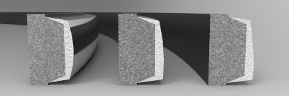


Rectangular rings
are normally used as compression rings in the 1st ring groove with different shapes of the running surface. This surface can be symmetrical or asymmetrical with a barrel-shaped design that creates a lubricating slot. Thus, the piston ring does not touch the surface of the liner.
Taper faced rings
match the shape of the liner quickly because of the small contact surface. The "running-in time" of these rings is much shorter; the same effect can be reached by using asymmetric design as described above.
Key stone rings
are used if cracking of fuel and/or lube oil residues can occur. Due to the fact that these rings are rotating permanently the residues were removed out of the ring groove. The key stone ring follows the cylinder wall springy and so the tightness between piston and liner is very good.Make sure that your fuel (we assume it´s HFO) stays at
5.2.2 Oil scraper rings
This piston ring is located in the lowest ring groove. Spring supported, he controls the thickness of the lube oil film at the wall of the cylinder liner.
- Too high contact pressure creates a too thin film and both, the oil scraper ring and the cylinder liner will be worn out earlier.
- Too low contact pressure creates a too thick film and more lube oil will be burnt; thus, the lube oil consumption increases and carbon deposits will be formed.
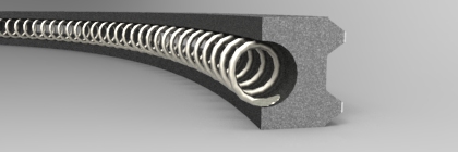
There are different designs of piston rings (1-piece slotted rings in different shapes, 2-piece coil spring rings and 3-piece rings). In modern 4-stroke Diesel engines 2-piece coil spring rings are used.
5.3 How to detect damages at the piston rings
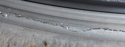
5.3.1 High crankcase pressure due to blow by of exhaust gas

In case of a problem with the piston ring (for what final reason ever), the sealing between the piston and the liner is not sufficient anymore. As a result, the hot exhaust gases are passing the combustion chamber downwards into to the crankcase.
If then -in sequence- the pressure inside the crankcase exceeds 20 mbar, it must be figured out which cylinder has lost his tightness. This can be done by measuring the compression pressure of each single cylinder.
The tightness must be repaired immediately because the hot exhaust gases can release an explosion inside the crankcase.
The crankcase pressure (please see also Part 3 of our article series) should be measured and recorded every 3 month at least.
Reasons for high crankcase pressure - among possible other ones - are:
- Stucked piston ring
- Broken piston ring
- Worn cylinder liner
- Worn piston ring
- Worn piston ring groove
- Slots of the rings are partially
or complete in the same position
5.3.2 High lube oil consumtion
If something is wrong with the piston rings, the lube oil consumption of the engine will increase due to a too thick oil film on the surface of the liner which burns during the combustion process.
5.3.3 Water in the fuel
As we already described in Part 4 -§ 4.3.3 of our article series, the water content in the fuel can be too high; due to a malfunction or an inproper maintenance of the separators. If this happens, sulphuric acid is formed which attacks and destroys initially the coating and later on the base material of the ring.
In the consequence, the life time of the piston ring will be decreased significantly due to the missing wear protection of the piston ring.
5.4 Preventive maintenance at piston rings
5.4.1 Prevention of carbon residues
As already mentioned above, the contact pressure - or more precisely: the radial tension - between the piston rings and the cylinder liner should be as equal as possible around the complete cylinder.
In order to fulfill this requirement, the piston rings must have the chance to move in the ring grooves constant- and continuously.
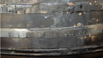
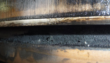
Explanation: Carbon = A mixture of unburned hydro-carbons, residues of burned lube oil and ashes. The reason for the formation of carbon, respectively carbon deposits has been described already in Part 4 - §4.3.1 of our article series.
If the amount of carbon is too high, it will clog the ring grooves step by step. Due to the transferred heat from the piston crown a compound - hard as stone - will be formed and the piston ring is sticking in his groove.
Now the piston ring cannot move/rotate anymore, will be overloaded at certain areas ...and propably break finally.
Prevention against carbon deposits caused by insufficient lube oil treatment
The lube oil in a power plant- or marine Diesel engine engine has a couple of specific "enemies" - beneath others:
- Carbon from the combustion process and residues of burned lube oil
- Water from the intake air
- Water which is produced during the burning process
- Sulphuric acid whichis formed out of the sulphurous acid
These are transferred into the lube oil on the surface of cylinder liner. If the concentration of these is too high the oil film on the liner will be affected and the particles are accumulated in the piston ring grooves. The movement of the piston rings in the ring grooves will be disturbed by these deposits and at the end of the day the rings will stick in the ring grooves....Game over !
Correct lube oil treatment in order to prevent sticking piston rings
- Continuous operation of the lube oil separators,
even if the engine is not running for a short time - Separation temperature 95°C
- Lube oil automatic filter in function with sound candles
- Lube oil analysis on a regular base
5.4.2 Worn piston ring grooves
At each engine inspection, when the pistons are removed as well, the height of the piston ring grooves have to be measured carefully around the complete circumference. If the wear limits have been reached already, the piston crowns must to be changed.
Reason of excessive wear of the grooves are abrasive particles of the fuel which are concentrated in the lube oil; the fuel should be analyzed against cat-fines, ashes, carbon residues and metallic elements.
5.4.3 Correct installation of piston rings
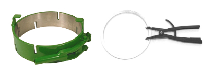
Below 3 little tips from Stefan and Heinz about how to deal with piston rings:
- your spare rings should be stored in a flat position, packed as supplied
and in a dry and clean atmosphere. - always use a suitable clamp tool for dismantling and mounting of the rings
- ensure that the ring slots are not on top of each other when assembled
in the piston crown
6. Summary
Piston rings are small items which have to bear a high responsibility. Thus, make sure that they are always in good condition because stuck or broken rings can create at least high lube oil consumption, but also piston seizures and other disasters.
....to be continued with Part 6 - Piston pin
Part 6 - Piston pin
6.1 Introduction
The piston pin -also known as the gudgeon pin- transfers the entire generated power out of the combustion process from the piston, via the connecting rod down to the crankshaft. Due to the fact that the piston pin does not rotate, he is the engine component that have to withstand the highest stresses in engine operation.
In this chapter, we will give answers to the following questions:
- Why are piston pins subject to crack during engine operation ?
- How to avoid high wear and tear of the gudgeon pins ?
- How to avoid subsequent damages caused by cracked gudgeon pins ?
6.2 Pistons pin function
The piston pin connects the piston and the connecting rod and must withstand extremely high loads in changing directions. It is commonly made out of case-hardening or nitraded steel with a hardened, smooth ground and polished surface.
In order to withstand the occuring loads out of the combustion process as well as the continuous increasing firing pressures, it is essential to permanently optimize the load-bearing capacity of this component..
Piston pins are characterized by precision, application diversity and the highest material quality.
Due to the oscillating forces of the ignition pressure and mass inertia forces in the opposite direction, the piston pin is bent through, oval-shaped and subjected to shear. The piston pin boss can be damaged by excessively large deformations of the piston pin, which can lead to the complete destruction of the piston.
Only in the case of small bolt deformations, the stresses remain below the permissible values.
The piston pin is mounted for power transmission in the pin bore of the piston and the connecting rod. The optimal clearance between piston pin and pin boss as well as connecting rod bush is very important for the function. Also the surface roughness has to be very low. Therefore, it is recommended for checking this on a regular basis.
For high speed engines, with stresses higher than in medium speed engines, coatings made of DLC (Diamond-like-Carbon) have been developed to minimize the friction between piston pin and connecting rod respectively their bearing bushes.
6.2 Piston pin damage
In order to prevent damage of a piston pin (gudgeons pin) the following measures shall be done.
Dimensional measurement
After engine maintenance and before the gudgeon pins are reinstalled, the diameter and ovality of each single pin should be checked and compared with the recommended wear and ovality limits of the engine maker.
Worn out pins may cause vibrations, respectively micro vibrations. Vibrations then will consequently cause damages at the bearing bushes of the connecting rod and the pin iteself.
Crack test of gudgeon pins
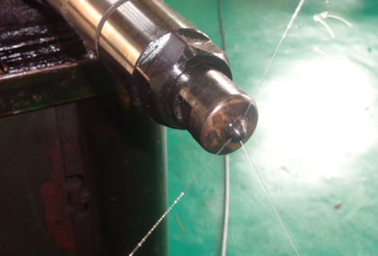
In addition to the dimensional check (wear and tear control) , we highly recommend - especially at piston pins with oil bores - to carry out a liquid penetrant crack test before the pin will be installed.
This test should also be carried out if the piston pin is new ! It is reported and we can confirm that from our own experience as well, that -very seldom but sometimes- faulty material was used by the manufacturer.
Piston pin damage caused by cavitation
Whatever has been made wrong during the assembling of a new or serviced piston crown on a piston skirt, will result into a small but continious movement between the seat areas of those parts.
As a consequence of this movement, cavitation at the surface of the piston pin will occur.
This cavitation is the result of high pressure accelarations in the lube oil. In the accelartion phase of this process a vacuum will be generated for milliseconds and implode; small material particles are teared out of the surface of the piston pin.
6.3. Summary
A piston pin transfers the entire power out of the combustion process from the piston, via the conrod, to the crankshaft and is the most stressed part of an engine. Therefore, the pin have to be checked against wear and tear carefully and on a regular basis.
Crack tests - as an important part of your planned maintenance schedule- are reducing the risk of broken pins and (like always and here again) a good lube oil treatment prevents high wear and tear at the piston pin.
....to be continued with Part 7 - Connecting rod
Part 7 - Connecting rod
7.1 Introduction
The connecting rod transfers the entire generated power out of the combustion process from the piston pin to the crankshaft and converts the reciprocating energy into rotating energy that drives either the propeller or the generator.
Within this chapter, we will give answers to the following questions:
In this chapter, we will give answers to the following questions:
- Is it possible to overhaul connecting rods ?
- How to prevent engine damages caused by e.g. loose conrod bolts?
7.2 Connecting rod function
The “connection piece” between the piston and the crankshaft is the connecting rod. Like all other engine parts that are directly involved into the combustion process, the connecting rod is highly stressed. The conrods alternating, comparative stress is mainly feeded by 3 different forces:
- the acceleration force, from the combustion process
- the mass force, from the piston and the piston pin
- the bending force, caused by the conrod angle
With a share of approximately 80%, the connecting rod shaft is mainly loaded by dynamically acting compression stresses out of the combustion process. The remaining 20% are dynamically acting bending loads. This results in a very complicate stress profile in the connecting rod eye (or small end) while engine operation.
The connecting rod shaft can be manufactured in a "H"- or "O-profile" (round cross section). Today´s engines - with high specific outputs - are equipped with fully machined conrods. For manufacturing reasons, they have an O-profiled shaft.
For the lubrification of the piston pin as well as for the piston cooling, the conrod shaft is very often drilled longitudinally.
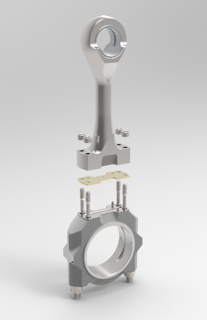
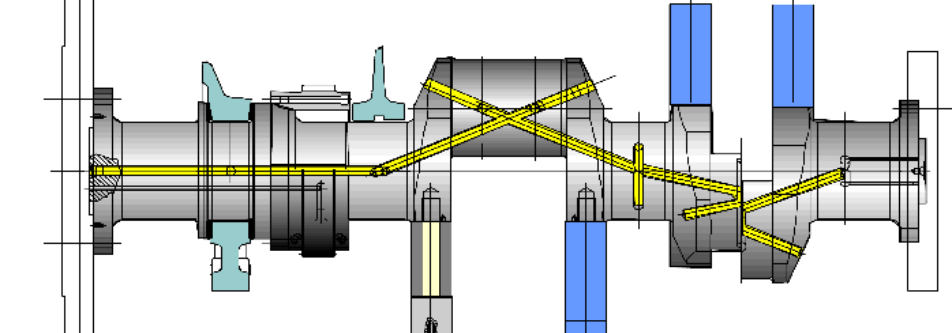
The upper end of the connecting rod is the connecting rod eye. This accommodates an undivided piston bolt bearing - the so called small end bearing. The lower end of the connecting rod is divided into two halves, as the connecting rod is guided through the cylinder from above - the so called big end bearing.
Initially the big end bearings were divided horizontally. When the specific output of the engines increased, larger surfaces for the bearing became necessary and they developed conrods with diagonally splitted big ends in order to pull the conrod upwards with its foot through the cylinder liner.
In order to avoid that the big end bearing housing must be opened during maintenance of the piston, todays modern connecting rods are divided between conrod shaft and big end bearing housing. Additionally, an intermediate plate allows to change the compression ratio of the engine by different thickness of this plate.
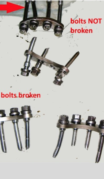
The screwed connection of the big end bearing housing is one of the most difficult connections for screws due to the high asymmetric load on them. This lead into dynamic bending stresses, that must be handled by the tightening forces. Because of this, the tightening procedure needs extremely high attention.
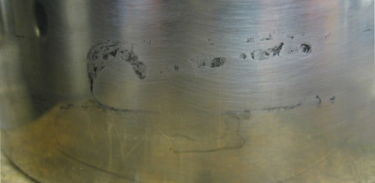
Due to the cranking of the conrod during combustion and compression - inside the cylinder - the big end bearing is subject to asymmetric forces which creates asymmetric and dynamic wear and tear. Therefore, the ovality of the big end bearing houses has to be checked on a regular basis. Due to the high forces, the mating surface between the lower half and the upper half of the big end bearing housing need´s the highest grade of planarity, in order to avoid fretting wear and tear.
In case of diagonally split big ends shearing forces have to be absorbed by means of a toothed joint face.
7.3 Preventive maintenance of Connecting Rods
The exact dimensions of the connecting rod, as well as his geometrie (e.g. the ovality of the big end bearing housing) shall be checked on a regular base during each maintenance. The required measuring report is part of the engine instruction manual from your engine manufacturer in most cases.
Dimensions and condition of the connecting rod
The mating surfaces of the bolts and the threads shall be in proper condition and not be affected by rough handling, because small damages can be the starting point of fatigue cracks.
Note: New conrod bolts are cheaper.... than a new engine !
Whenever it is for certain for the most of us...but here´s our recommendation about what is necessary to get reliable measurements for the right decisions:
- measuring e.g. the diameter and ovality of a big end bearing
housing requires full tightened connecting rod bolts with
assembled connecting rod shaft ! - requires also to make use of the correct lubricant for bolts and nuts
(in accordance to the advise from your engine manufacturer)
=> see Sidekick 1 - requires also that the temperature of the housing, the calibrating
and the measuring device is as equal as possible
=> see Sidekick 2 - requires also to calibrate your measurement device infront of the
measurement
Sidekick 1
If you want to ensure proper function of an engine component like f.e. piston, cylinder head and of course as well the connecting rod, it is essential to make use of the correct lubricant for the assembling parts (bolt, nuts etc.)
To ensure this, all engine manufacturers "Instruction Manual" contains the information what kind of lubricant you must use. It is important to understand that this is an instruction and not just a recommendation that you can ignore or neglect if the correct lubricant is not available. Ignoring or neglecting this instruction may result in a significant deviation of the required tightening forces! And if this happens... good luck for your engine...
How much lubricant should I use ? Much helps much ? No, it´s quite opposite. The job of a lubricant is to reduce the friction between the threads of bolts and nuts. A thin layer of the lubricant is enough; unless it is otherwise stated by the engine manufacturer. In our final assembling of pistons, we use (don´t laugh) tooth brushes for the smaller and bottle brushes for the larger threads to ensure just a thin layer of the lubricant.
Need an example? Here it is: Assembling a MAN 16/24 piston with too much Molykote on the thread of the bolts (dipping the bolts into the Molykote) will result in a loosening torque that is more than 40% lower than required. As a consequence, the piston crown becomes loose in engine operation. We have seen this cases on board of several vessels when the crown was changed by the crew some years ago...
Sidekick 2
As the size of the measurement to be measured increases, the measuring error also increases at deviating temperatures between the engine component, the calibrating and the measuring device.
A temperature difference of only 6°C (assumed 28°C of the housing and 22°C of the measuring device) between a big end bearing housing with an assumed bore diameter of e.g. 450 mm and the measuring device will result in a measuring error of appr. 0,03 mm ! The "as new" tolerance of in this bore range usually is only +0.04 mm.
Condition of connecting rod bolts
The surface of the bolts and the threads shall be in proper condition and not be affected by rough handling: Small damages can be the starting point of fatigue cracks.
NEVER ! use new and used assembly components at the same conrod.
Correct tightening of connecting rod bolts
Make sure that the bolts are tightened in complete accordance to the instructions of your engine manufacturer in all regards like e.g. - the tightening stages, the correct lubricant and of course => no use of hammers and other heavy tools.
7.4 Reconditioning of connecting rods by SECO
To our customers SECO and MMS are offering the overhaul of connecting rods for the supported engine types.
The reconditioning procedure that we are carrying out consists of:
- disassembly and cleaning of the connecting rod
- visual inspection
- measuring of the diameters and ovality of the
- big end bearing housing in full tightened condition
- gudgeon pin bearing bush (small end) - grinding of the mating surface of the intermediate plate (if applicable)
- disassembling and magnetic powder crack detection of the complete
connecting rod. - cleaning
- line boring
- all assembly parts will be replaced by new once
7.5. Summary
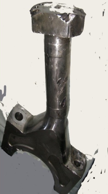
The mechanical stress to the connecting rod is enormous and a damaged conrod will release a disaster – mostly the total loss of the engine. Therefore, correct maintenance is essential.
....to be continued with Part 8 - Crankshaft
Part 8 - Crankshaft
Introduction
Let´s start wit the basics of the crankshaft initially...
In all reciprocrating engines, the crankshaft is converting the linear reciprocating motion of the piston into the rotational motion of the crankshaft. While engine operation, the mass forces of the reciprocating pistons - thus generated by the explosive combustion process - will be converted into a torque. This torque then is used to drive either a generator or a propeller that is attached to the engine.
In order to generate a motion, respectively a torque that is as unique as possible, the crankshaft is connected to a flywheel or a torsional damper in order to reduce the pulsating charakteristcs of the 4-stroke-cycle and to cover the elasticity of the crankshaft itself.
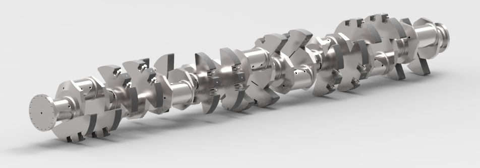
8.1 Crankshaft
Covering the complete range of modern combustion engines, the crankshafts are either made from nodular cast iron (e.g. Automotive industrie) or from alloyed steel (e.g. large bore Power Plant- and Marine Diesel Engines). Small sized crankshafts will be drop-forged in one piece and finally machined. Large crankshaft will be rough-forged as individual parts; correctly aligned and positioned in the right direction and finally machined.
Crankshafts of large bore Power Plant- and Marine Diesel Engines can be divided in general in two different categories:
- Partly built crankshaft - the individual manufactured cheeks are assembled by shrinkage.
- Completely built crankshaft - all individual manufactured shaft pieces are assembled.
All modern Power Plant- and Marine Diesel Engines crankshafts are usually made from alloyed steel with a tensile strength of 800 to 900 n/mm². Small crankshafts are flame or induction hardened. In order to get a higher internal compression stress the transition area between pin and cheeks has to be hardened as well.
Inside the crankshafts are borings in order to feed lube oil to the main and big end bearings and the conrod.
If a new crankshaft has been designed, the mass forces, acceleration forces, torsional forces and bending moments, used for the design of the crankshaft, must be checked and approved by a Classification Society; if the crankshaft, respectively the engine will be operated on seagoing vessels.
In addition to this, the material itself, whose mechanical properties, all heattreatments and all related manufacturing processes needs the approval of the classification society as well.
8.2 Inspection and Maintenance of Crankshafts
8.2.1 Crankshaft Measuremnent
It is very important that the position of the crankshaft within the engine is absolute correct. Otherwise the crankshaft itself and/or the main- and big end bearings will be damaged due to the high forces, respectively the high stresses that are introduced into the crankshaft while engine operation.
The correct position of the crankshaft within the engine has to be ensured by an absolut correct alignment.
The correct alignment of the crankshaft will be influenced by the type of coupling that is installed between the engine and the generator, respectively between the engine and the gearbox.
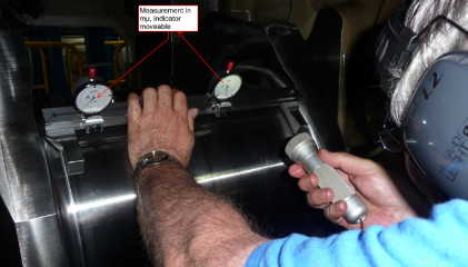
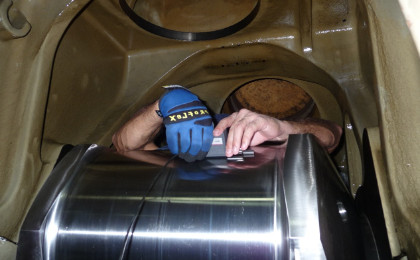
As already mentioned, the correct position of the crankshaft within the engine has to be ensured at any time. In order to check this position, the distance between each pair of cheeks during one complete rotation has to be measured. If the difference in distance between the individual positions is out off the limits, the engine alignment must be corrected. Therefore, the reference measures out of the vessels/engines sea trial respectively the engines commissioning, can be taken.
The crankshaft deflection measurement has to be carried out
- Before and after docking of the vessel
- Damage or grounding of the vessel
- If a deformation of the engine foundation was detected
- If the wear and tear of the engine bearings are abnormal high or uneven (more wear and tear at the edges than in the middle).
8.2.2 Inspection of Counterweight Fastenings
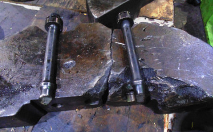
Even if it should be self-evident, we strongly recommend you to include the check of correct tightened screw connections between the counterweights and the crankshaft into your preventive maintenance procedure. This to ensure, that this important check will be carried out on a regular basis.
If a counterweight becomes loose the screws will be overloaded. Sooner or later, the screw will be overloaded and break....for anyhow. The most probably consequence will be the total loss of your engine.
8.2.3 Cracks
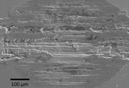
During the standard inspection or after changing the main- and/or big end bearings, it has to be checked if there are any micro-cracks at the edges between the cranks, the shaft and conrod pin. These cracks are realy very dangerous and can be the starting point of a fatigue crack.
8.2.4 Lube oil treatment and Lube oil viskosity
Details regarding lube oil treatment will be described in a following chapter) Lube oil polluted by carbon residues will increase wear and tear of the main and big end bearings. If a bearing is completely worn out the bearing may rotate and the crankshaft will be affected: If the cooling system is not working properly the temperature of the oil will be too high and the viscosity of the oil too low: it loses its lubrication capability and the wear and tear of the bearings will increase as well.
8.3 Repair works
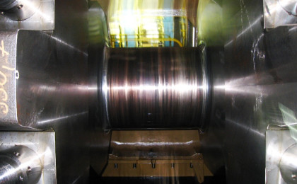
If the shaft or the pins are affected by overheating due to worn out bearings or due to rotating of the bearings the crankshaft can be ground by a specialized company in – situ or in a workshop. In that case, oversize bearings have to be used in order to compensate the loss of diameter of the shaft or the pin. Crankshafts are designed for that procedure; however, it has to be checked if the remaining strength is sufficient for the considered power.
Unevenness of the bearing areas can be measured at side by experienced personal by means of a profile meter (known as Perthometer as well).
8.4 Summary
The dynamic stresses that are generated while engine operation and introduced into the crankshaft, are extremly high.
However, if the crankshaft will be maintained properly (deflection measurement, proper lube oil treatment, counterweight fastening controlled), the life time of the crankshaft will be the same as the life time of the engine.
....to be continued with Part 9 - Cylinder liner
Disclaimer
We explicitly point out that all the technical recommendations, that we publish in our website in the section "Technical Support", have been created with the greatest possible care; however, they.... Please, read the complete disclaimer.

")
